En
En
 فا
فا
UPS
|
UPS
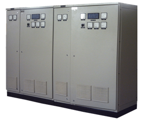
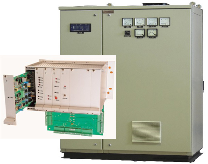
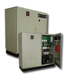
Sepahan method electronic is able to design & manufacture high power industrial online Uninterruptable Power Supplies (UPS) up to 500KVA power. All stages is done by our experts, so various features can be add according to customer request.
|
General UPSs |
|
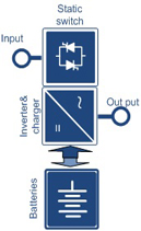
LINE INTERACTIVE UPS
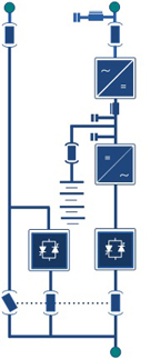
The line interactive UPS The line interactive UPS, illustrated in Figure in front, is the most common design used for small size of UPS in the market for use for comuter server and home ups. In this type, the battery-to-AC power converter (inverter) is always connected to the output of the UPS. Operating the inverter in reverse during times when the input AC power is normal provides battery charging. When the input power fails, the transfer switch opens and the power flows from the battery to the UPS output. With the inverter always on and connected to the output, this design provides additional filtering and yields reduced switching transients when compared with the standby UPS topology. In addition, the line interactive design usually incorporates a tap-changing transformer. This adds voltage regulation by adjusting transformer taps as the input voltage varies. Voltage regulation is an important feature when low voltage conditions exist, otherwise the UPS would transfer to battery and then eventually down the load. This more frequent battery usage can cause premature battery failure. However, the inverter can also be designed such that its failure will still permit power flow from the AC input to the output, which eliminates the potential of single point failure and effectively provides for two independent power paths. High efficiency, small size, low cost and high reliability coupled with the ability to correct low or high line voltage conditions make this the dominant type of UPS in the 0.5-5 kVA power range. |
|
|
STAND BY FERRO UPS
The standby-ferro UPS The standby-ferro UPS was once the dominant form of UPS in the 3-15 kVA range. This design depends on a special saturating transformer that has three windings (power connections). The primary power path is from AC input, through a transfer switch, through the transformer, and to the output. In the case of a power failure, the transfer switch is opened, and the inverter picks up the output load. In the standby-ferro design, the inverter is in the standby mode, and is energized when the input power fails and the transfer switch is opened. The transformer has a special "ferroresonant" capability, which provides limited voltage regulation and output waveform "shaping". The isolation from AC power transients provided by the ferro transformer is as good as or better than any filter available. But the ferro transformer itself creates severe output voltage distortion and transients, which can be worse than a poor AC connection. Even though it is a standby UPS by design, the standby-ferro generates a great deal of heat because the ferro-resonant transformer is inherently inefficient. These transformers are also large relative to regular isolation transformers; so standby-ferro UPS are generally quite large and heavy. Figure 2 Line interactive UPS The Different Types of UPS Systems Schneider Electric – Data Center Science Center White Paper 1 Rev 7 4 Standby-ferro UPS systems are frequently represented as on-line units, even though they have a transfer switch, the inverter operates in the standby mode, and they exhibit a transfer characteristic during an AC power failure. Figure 3 illustrates this standby-ferro topology. |
|
 |
|
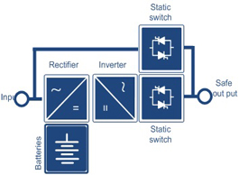
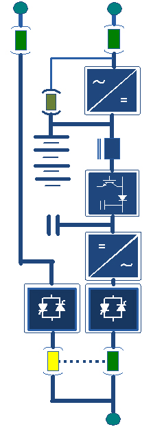
DOUBLE CONVERSION ONLIE UPS
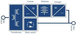
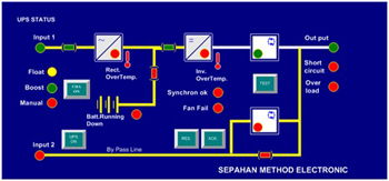
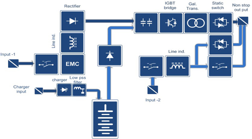
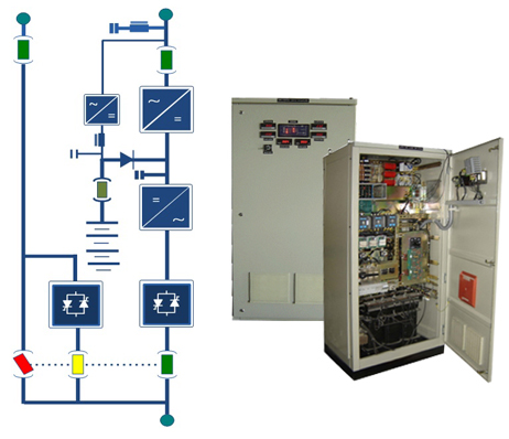
In double conversion type ups the primary source will rectified to dc bus which is connected to the batteries and then from dc bus the power should convert to Ac by the proper inverter and will transfer to out directly or through transformer and by passing through transfer switch ,in this case the failure of the input AC or any interruption does not affect on the load because any interruption such as frailer or big variation will compensate by batteries ,and clearly during normal condition if happened any over load or short circuit in the load the transformer switch which one is connected to bypass line or primary source will intervene and therefore without any interruption inverter will protect from overload or short circuit and the main source will be able to remove the case and do in to function main circuit as before ,Double Conversion On-Line UPS should be design specially for industrial us as the full galvanic isolatedby means of power transformer in input and output of UPS. |
|
|
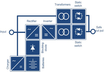
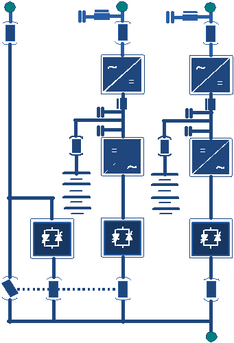
DOUBLE CONVERSION GALVANIC ISOLATED ONLIE UPS
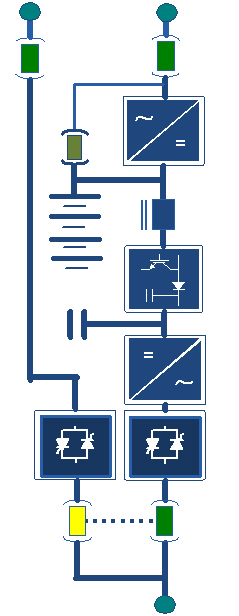
As descibed before the double conversion ups ,the input power performed in to dc power in order eliminate any fault and intrrupt and put together with batteries for making the safe and sufficent energy in dc bus and then in the inverter part this energy will convert to ac and deliver to load by means of transfer switch. In the double convesion galvanic isolated will use the proper power transformer in order to isolate galvaniclly output from input. this type of ups is more expensive respect of other types and will be use for important part of industry . |
|
 |
|
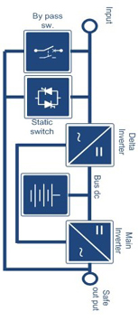
DELTA CONVERSION ONLIE UPS
The delta conversion on-line UPS This UPS design, illustrated in Figure 5, is a newer, 10 year old technology introduced to eliminate the drawbacks of the double conversion on-line design and is available in sizes ranging from 5 kVA to 1.6 MW. Similar to the double conversion on-line design, the delta conversion on-line UPS always has the inverter supplying the load voltage. However, the additional delta converter also contributes power to the inverter output. Under conditions of AC failure or disturbances, this design exhibits behavior identical to the double conversion on-line. Figure 4 Double conversion on-line UPS The Different Types of UPS Systems Schneider Electric – Data Center Science Center White Paper 1 Rev 7 6 DELTA CONVERTER MAIN INVERTER AC DC DC AC STATIC BYPASS SWITCH DELTA TRANSFORMER ` A simple way to understand the energy efficiency of the delta conversion topology is to consider the energy required to deliver a package from the 4th floor to the 5th floor of a building as shown in Figure 6. Delta conversion technology saves energy by carrying the package only the difference (delta) between the starting and ending points. The double conversion on-line UPS converts the power to the battery and back again whereas the delta converter moves components of the power from input to the output. |
|
Design Samples |
MPSU-150
|
INPUT DATA : |
|
|
|
Rated Voltage : |
380 - 230 Volt 3Phase ±15% |
|
|
Rated Frequency : |
50 Hz ±5% |
|
|
OUTPUT DATA : |
||
|
Rated Voltage : |
220/380 V 1/3Phase ±2% |
|
|
Voltage Regulation : |
static : ±1% dynamic : ±5% |
|
|
Rated Frequency : |
50 Hz |
|
|
Frequency Regulation : |
operating with main : ±0.5% operating with battery : ±0.0001 |
|
|
Over Load Capacity : |
125% for 15 & 150% for 1" |
|
|
Starting Power : |
200% for 100 ms |
|
|
Total Harmonic Distortion (THD) : |
<3% (optional 1% with derating of power) |
|
|
Max Unbalanced Load : |
<30% |
|
|
Efficiency : |
>85% |
|
|
DC BUS & BATTERIES : |
||
|
Batteries Voltage : |
120 , 240 , 360 Volt |
|
|
Charging unit : |
Trough main rectifier & Filters |
|
|
Charging method : |
Constant current,Constant voltage |
|
|
SYSTEM DATA : |
|
||
|
Protection Class : |
IP20 |
||
|
Operating Temperature : |
0 - 40° C |
||
|
Relative Humidity : |
0 - 95% |
||
|
Noise Level : |
<40 dB |
||
|
Paralleling : |
Up to 4 units |
||
|
Autonomy : |
On request |
||
|
Batteries : |
Seald , Lead acid , Ni - Cd |
||
|
MTBF : |
>100,000 h |
|
|
|
BATTERIES: |
|
|
|
|
Batteries Fuse protected |
|||
|
Seald , Lead - acid or Nikel - cadmium |
|||
|
BY PASS LINE: |
|||
|
Network circuit breaker |
|||
|
By pass Isolated by transformer |
|||
|
Static switch Module-net |
|
||
|
Maintenance by pass switch |
|||
|
AVR ( option) |
|||
|
INDICATORS: |
|||
|
Input Voltage |
|||
|
Input Current |
|||
|
Output Voltage |
|||
|
Output Current |
|||
|
Output frequency |
|||
|
DC Voltage |
|||
|
Charging Current
|
|||
|
*All above metering should bewith classic analoge meter or led Display |
|||
|
ALARMS: |
|||
|
Under - Over network |
|||
|
Output Fault |
OPTION: | ||
|
Overload |
paralleling Devices |
|
|
|
Short Circuit |
SNMP CARDS |
|
|
|
Synchrony Fault |
RS232/RS485 Interface |
|
|
|
Battery Running Down |
|
|
|
|
Earth Fault
|
|
|
|
|
*All above alarm should be as with special alarm display or lighting announcment panel as the option
|
|
||

MPSU-500
|
INPUT DATA : |
|
|
|
Rated Voltage : |
400 Volt 3Phase ±15% |
|
|
Rated Frequency : |
50-60 Hz ±5% |
|
|
OUTPUT DATA : |
||
|
Rated Voltage : |
380 V 1/3Phase ±2% |
|
|
Voltage Regulation : |
static : ±1% dynamic : ±5% |
|
|
Rated Frequency : |
50 - 60 Hz |
|
|
Frequency Regulation : |
operating with main : ±0.5% operating with battery : ±0.0001 |
|
|
Over Load Capacity : |
125% for 15 & 150% for 1" |
|
|
Starting Power : |
200% for 100 ms |
|
|
Total Harmonic Distortion (THD) : |
<3% (optional 1% with derating of power) |
|
|
Max Unbalanced Load : |
<20% |
|
|
Efficiency : |
>90% |
|
|
DC BUS & BATTERIES : |
||
|
Batteries Voltage : |
360 -432 Volt |
|
|
Charging unit : |
Using separate charger |
|
|
Charging method : |
Constant current,Constant voltage
|
|
|
SYSTEM DATA : |
|
|
|
Protection Class : |
IP20 |
|
|
Operating Temperature : |
0 - 40° C |
|
|
Relative Humidity : |
0 - 95% |
|
|
Noise Level : |
<40 dB |
|
|
Paralleling : |
Up to 4 units |
|
|
Autonomy : |
On request |
|
|
Batteries : |
Seald , Lead acid , Ni - Cd |
|
|
MTBF : |
>100,000 h |
|
BATTERIES: |
INDICATORS: |
INVERTER: |
|
Batteries Fuse protected |
Input Voltage |
Input circuit breaker |
|
Seald , Lead - acid or Nikel - cadmium |
Input Current & voltage & Freq. |
Heavy duty IGBTs module |
|
BY PASS LINE: |
Output Current & Voltage & Freq. |
Output transformer |
|
Batteries Voltage |
Output AC filter |
|
|
Network circuit breaker |
Batteries Charging current |
STATIC SWITCH Module-inv |
|
Network-input inductance |
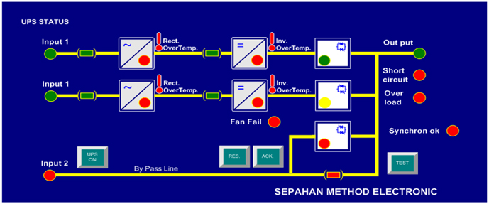
UPS Situation MIMIC |
|
|
Static switch Module-net |
|
The MPS Series consist of : |
|
Maintenance by pass switch |
RECTIFIER: |
|
|
AVR ( option) |
EMI filter | |
|
|
Input circuit breaker | |
|
ALARMS on Mimic panel: |
Thyristor 6 pulse Rectifier bridge | |
|
Under - Over network |
DC filter(3% ripple with &without batteries) |
|
|
Output Fault |
||
|
Overload |
OPTION: |
|
|
Short Circuit |
paralleling Devices |
|
|
Synchrony Fault |
SNMP CARDS |
|
|
Battery Running Down |
RS232/RS485 Interface | |
|
Earth Fault (optional) |
||
|
*For detail please refer to Alarm panel |
||
|
|
|
|
SMPS-50
|
INPUT DATA : |
|
|
|
Rated Voltage : |
380 Volt 3Phase ±15% |
|
|
Rated Frequency : |
50-60 Hz ±5% |
|
|
OUTPUT DATA : |
||
|
Output Power : |
5, 10, 15, 20, 30, 50 KVA |
|
|
Rated Voltage : |
380 V 1/3Phase ±2% |
|
|
Rated Frequency : |
50 - 60 Hz |
|
|
Frequency Regulation : |
operating with main : ±0.5% operating with battery : ±0.0001 |
|
|
Over Load Capacity : |
125% for 15" & 150% for 1" |
|
|
Starting Power : |
200% for 100 ms |
|
|
Total Harmonic Distortion (THD) : |
<3% (optional 1% with derating of power) |
|
|
Max Unbalanced Load : |
<20% |
|
|
Eiffciency : |
>89% |
|
|
DC BUS & BATTERIES : |
||
|
Batteries Voltage : |
24 -120 Volt |
|
|
Charging unit : |
Using separate charger |
|
|
Charging method : |
Constant current,Constant voltage |
|
|
SYSTEM DATA : |
|
ALARMS on Mimic panel: |
|
Protection Class : |
IP20 |
Under - Over network |
|
Operating Temperature : |
0 - 40° C |
Output Fault |
|
Relative Humidity : |
0 - 95% |
Overload |
|
Noise Level : |
<40 dB |
Short Circuit |
|
Paralleling : |
Up to 4 units |
Synchrony Fault |
|
Autonomy : |
On request |
Battery Running Down |
|
Batteries : |
Seald , Lead acid , Ni - Cd |
Earth Fault (optional) |
|
MTBF : |
>100,000 h |
*For detail please refer to Alarm panel |
|
BATTERIES: |
INDICATORS: |
INVERTER: |
|
Batteries Fuse protected |
Input Voltage |
Input Isolator switch |
|
SEPARATE BATTERIES CHARGER |
Input Current & voltage & Freq. |
Heavy duty IGBTs module |
|
BATTERIES BLOCKING THYRISTORS |
Output Current & Voltage & Freq. |
Output AC filter |
|
Seald , Lead - acid or Nikel - cadmium |
Batteries Voltage |
STATIC SWITCH Module-inv |
|
BY PASS LINE: |
Batteries Charging current |
|
|
UPS Situation MIMIC |
The SMPS-50 ONLINE UPS Series consist of : |
|
|
Network circuit breaker |
|
RECTIFIER: |
|
Network-input inductance |
EMI filter |
|
|
Static switch Module-net |
Input circuit breaker |
|
|
|
Input Inductance |
|
|
BUCK BUST: |
Diode base Rectifier bridge | |
|
Buck boost Inductances |
||
|
Buck boost IGBTs |
OPTION: | |
|
Blocking diodes |
SNMP CARDS | |
|
Capacitors bank |
RS232/RS485 Interface | |
|
|
|
SMPS-1-20
|
INPUT DATA : |
|
|
|
Rated Voltage : |
380 Volt 3Phase ±15% |
|
|
Rated Frequency : |
50-60 Hz ±5% |
|
|
OUTPUT DATA : |
||
|
Output Power : |
5, 10, 15, 20 KVA |
|
|
Rated Voltage : |
380 V 1Phase ±2% |
|
|
Rated Frequency : |
50 - 60 Hz |
|
|
Over Load Capacity : |
125% for 15" & 150% for 1" |
|
|
Starting Power : |
200% for 100 ms |
|
|
Total Harmonic Distortion (THD) : |
<3% (optional 1% with derating of power) |
|
|
Eiffciency : |
>92% |
|
|
DC BUS & BATTERIES : |
||
|
Batteries Voltage : |
24 to 120 Volt |
|
|
Charging unit : |
Using separate charger |
|
|
Charging method : |
Constant current,Constant voltage |
|
|
SYSTEM DATA : |
|
ALARMS on Mimic panel: |
|
Protection Class : |
IP20 |
Under - Over network |
|
Operating Temperature : |
0 - 40° C |
Output Fault |
|
Relative Humidity : |
0 - 95% |
Overload |
|
Noise Level : |
<40 dB |
Short Circuit |
|
Autonomy : |
50, 100, 150 AH |
Synchrony Fault |
|
Batteries : |
Dry acid |
Battery Running Down |
|
MTBF : |
>100,000 h |
Earth Fault (optional) |
|
|
|
*For detail please refer to Alarm panel |
|
BATTERIES: |
INDICATORS: |
INVERTER: |
|
Batteries Fuse protected |
Input Voltage |
Heavy duty IGBTs module |
|
SEPARATE BATTERIES CHARGER |
Input Current & voltage & Freq. |
Output AC filter |
|
BATTERIES BLOCKING THYRISTORS |
Output Current & Voltage & Freq. |
STATIC SWITCH Module-inv |
|
Seald , Lead - acid or Nikel - cadmium |
Batteries Voltage |
|
|
BY PASS LINE: |
Batteries Charging current |
|
|
UPS Situation MIMIC |
The SMPS-1-20 ONLINE UPS Series consist of : |
|
|
Network circuit braker |
|
RECTIFIER: |
|
Network-input inductance |
Input circuit breaker |
|
|
Static switch Module-net |
Input Filter |
|
|
|
Diode base Rectifier bridge |
|
|
BUCK BUST: |
||
|
Buck boost Inductances |
OPTION: | |
|
Buck boost IGBTs |
SNMP CARDS | |
|
Blocking diodes |
RS232/RS485 Interface | |
|
Capacitors bank |
||
|
|
|
MPSU-2X150
|
INPUT DATA : |
|
|
|
Rated Voltage : |
380-230 Volt 3Phase ±15% |
|
|
Rated Frequency : |
50 ±5% |
|
|
OUTPUT DATA : |
||
|
Rated Voltage : |
220/380 V 1/3Phase ±2% |
|
|
Voltage Regulation : |
static : ±1% Dynamic : ±5% |
|
|
Rated Frequency : |
50 Hz |
|
|
Frequency Regulation : |
operating with main : ±0.5% operating with battery : ±0.0001 |
|
|
Over Load Capacity : |
125% for 15" & 150% for 1" |
|
|
Starting Power : |
200% for 100 ms |
|
|
Total Harmonic Distortion (THD) : |
<3% (optional 1% with derating of power) |
|
|
Max Unbalanced Load : |
<30% |
|
|
Eiffciency : |
>85% |
|
|
DC BUS & BATTERIES : |
||
|
Batteries Voltage : |
120, 240, 360 Volt |
|
|
Charging unit : |
Through main rectifier & Filters |
|
|
Charging method : |
Constant current,Constant voltage |
|
|
SYSTEM DATA : |
|
ALARMS: |
|
Protection Class : |
IP20 |
Under - Over network |
|
Operating Temperature : |
0 - 40° C |
Output Fault |
|
Relative Humidity : |
0 - 95% |
Overload |
|
Noise Level : |
<40 dB |
Short Circuit |
|
Paralleling : |
Up to 4 units |
Synchrony Fault |
|
Autonomy : |
On request |
Battery Running Down |
|
Batteries : |
Seald , Lead acid , Ni - Cd |
Earth Fault |
|
MTBF : |
>100,000 h |
*All above alarm should be as with special alarm display or lighting announcment panel as the option |
|
BATTERIES: |
INDICATORS: |
INVERTER: |
|
Batteries Fuse protected |
Input Voltage |
Input circuit breaker |
|
Seald , Lead - acid or Nikel - cadmium |
Input Current |
Heavy duty IGBTs module |
|
|
Output Voltage |
Output transformer |
|
BY PASS LINE: |
Output Current |
Output AC filter |
|
Network circuit breaker |
Output frequency |
STATIC SWITCH Module-inv |
|
By pass Isolated by transformer |
DC Voltage |
|
|
Static switch Module-net |
Charging Current |
|
|
Maintenace by pass switch |
*All above metering should be with classic analoge meter or led Display |
|
|
AVR ( option ) |
||
|
|
|
|
|
The MPS Series consist of : |
||
|
RECTIFIER: |
||
| EMI filter | OPTION: |
|
|
Input circuit breaker |
Paralleling Devices |
|
| Thyristor 6 pulse Rectifier bridge | NMP CARDS |
|
| DC filter (3% ripple with & without batteries) | RS232/RS485 Interface |